
The servo system is driven by mechanical motion, the motor is the control object, the controller is the core, the power electronic power conversion device is used as the actuator, and the electric drive automatic control system is composed under the guidance of the automatic control theory. This type of system controls the torque, speed and angle of the motor, converting electrical energy into mechanical energy to achieve the motion requirements of the moving machine. Specifically, in the numerical control machine tool, the servo system receives the displacement and speed commands issued by the numerical control system. After transformation, adjustment and rectification, the motor and mechanical transmission mechanism drive the machine tool coordinate axes and spindles to drive the table and the tool holder. The linkage of the axes causes the tool to produce various complex mechanical movements relative to the workpiece, thereby machining the workpiece of complex shapes required by the user.
As the actuator of CNC machine tools, the servo system integrates power electronics, control, drive and protection, and has experienced the progress of digital pulse width modulation technology, special motor material technology, microelectronic technology and modern control technology. From stepping to DC, and then to the development of communication. There are many kinds of servo systems in CNC machine tools. This paper analyzes its structure and simple classification, and briefly discusses its technical status and development trends.
Second, the structure and classification of the servo system
From the basic structure, the servo system is mainly composed of three parts: controller, power drive, feedback device and motor (Figure 1). The controller adjusts the control amount according to the difference between the given value of the numerical control system and the actual running value detected by the feedback device; the power driving device acts as the main circuit of the system, and on the one hand, the electric energy in the power grid is applied to the electric motor according to the magnitude of the control amount. On the other hand, the magnitude of the motor torque is adjusted. On the other hand, the constant voltage constant frequency power supply is converted into the alternating current or direct current required by the motor according to the requirements of the motor; the motor is driven by the mechanical operation according to the power supply.
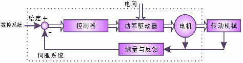
Figure 1 Structure of the servo system
The main components in Figure 1 vary widely, and any change in any of them can constitute different kinds of servo systems. According to the type of the drive motor, it can be divided into DC servo and AC servo; according to the different methods of controller implementation, it can be divided into analog servo and digital servo; according to the number of closed loops in the controller, it can be divided into Open loop control system, single loop control system, dual loop control system and multi-loop control system. Considering the application of servo system in CNC machine tools, this paper first divides it into feed servo and spindle servo according to the different transmission machinery in the machine tool, and then discusses the technical characteristics of different servo systems according to other factors.Third, the current status and prospects of the feed servo system
The feed servo takes the coordinates of the CNC machine as the control object and generates the cutting feed motion of the machine tool. For this reason, the feed servo is required to quickly adjust the movement speed of the coordinate axis and accurately perform position control. The specific requirements include wide speed range, high displacement accuracy, good stability and fast dynamic response. According to the motor used in the system, the feed servo can be subdivided into step servo, DC servo, AC servo and linear servo.
(1) Stepper servo system
Step servo is a control system that uses pulse signals to control and convert pulse signals into corresponding angular displacements. The angular displacement is proportional to the number of pulses, and the rotational speed is proportional to the pulse frequency. The rotational speed of the motor can be adjusted by changing the pulse frequency. If some of the windings remain energized after a shutdown, the system also has a self-locking capability. The stepping motor has a fixed number of steps per revolution, such as 500 steps, 1000 steps, 50 000 steps, etc. In theory, the step error will not be accumulated.
The stepping servo structure is simple and meets the needs of the digital development of the system, but the precision is poor, the energy consumption is high, the speed is low, and the power is higher, the moving speed is lower. In particular, step servos are prone to loss of step, making them mainly used for economical CNC machine tools and old equipment that require less speed and accuracy. However, the constant-wave drive, PWM drive, micro-step drive, ultra-micro step drive and hybrid servo technology developed in recent years have greatly improved the high and low frequency characteristics of stepper motors, especially with intelligent ultra-microsteps. The development of drive technology will take the performance of step servo to a new level.
(2) DC servo system
The working principle of DC servo is based on the law of electromagnetic force. Related to electromagnetic torque are two variables of main magnetic flux and armature current, which respectively control the excitation current and armature current, and can easily control torque and speed. On the other hand, from the control point of view, the DC servo control is a single-input and single-output single-variable control system. The classical control theory is completely applicable to this system. Therefore, the DC servo system has simple control and excellent speed regulation performance. The feed drive has dominated.
However, from the practical point of view, the DC servo motor introduces a mechanical reversing device. The cost is high, the fault is many, the maintenance is difficult, and the spark generated by the carbon brush often affects the production and generates electromagnetic interference to other equipment. At the same time, the commutation capability of the mechanical commutator limits the capacity and speed of the motor. The armature of the motor is on the rotor, making the motor inefficient and poorly dissipated. In order to improve the commutation ability and reduce the leakage inductance of the armature, the rotor becomes short and thick, which affects the dynamic performance of the system.
(3) AC servo system
For the defects of the DC motor, if it is treated as "inside", the winding of the electric drive is mounted on the stator and the rotor is a permanent magnet part, and the position of the magnetic pole is measured by the encoder on the rotor shaft, which constitutes a permanent magnet. The brushless motor, along with the practical application of the vector control method, makes the AC servo system have good servo characteristics. Its wide technical range, high speed accuracy, fast dynamic response and four-quadrant operation make its dynamic and static characteristics comparable to DC servo systems. At the same time, the weak magnetic high-speed control can be realized, the speed range of the system is widened, and the requirements of high-performance servo drive are adapted.
At present, the permanent magnet synchronous AC servo system is mainly used in the machine feed servo. There are three types: analog form, digital form and software form. The analog servo has a single purpose and only receives analog signals. The position control is usually implemented by the host computer. Digital servo can realize multi-purpose of one machine, such as speed, torque and position control. It can receive analog commands and pulse commands, and various parameters are set digitally with good stability. Has a rich self-diagnosis, alarm function. Software servo is a microprocessor-based all-digital servo system. It implements the monitoring program of servo motors of various control modes and different specifications and powers in software. When used, the user can set the code and related data to automatically enter the working state. With a digital interface, when changing the working mode and replacing the motor specifications, you only need to reset the code, so it is also called universal servo.
AC servo has occupied the dominant position of machine tool feed servo, and has been continuously improved with the development of new technology, which is embodied in three aspects. First, the power electronic devices in the system power drive device continue to develop toward high frequency, intelligent power modules are popularized and applied; second, based on the maturity of microprocessor embedded platform technology, it will promote the application of advanced control algorithms; It is the promotion of networked manufacturing mode and the maturity of fieldbus technology, which will enable network-based servo control.
(4) Linear servo system
The linear servo system adopts a direct drive method (Direct Drive). Compared with the traditional rotary transmission method, the biggest feature is that all mechanical intermediate transmission links between the motor and the workbench are eliminated, that is, the machine tool is fed into the transmission chain. The length is shortened to zero. This "zero-drive" mode brings performance indicators that cannot be achieved by the rotary drive method. For example, the acceleration can reach more than 3g, which is 10 to 20 times that of the conventional drive device, and the feed speed is 4 to 5 times that of the conventional one. From the working principle of the motor, the linear motor has various methods such as DC, AC, stepping, permanent magnet, electromagnetic, synchronous and asynchronous; and in terms of structure, there are moving coil, moving iron, flat and Cylindrical type. At present, there are mainly two types of high-precision high-frequency ring-stroke linear motors and high-thrust long-stroke high-precision linear motors applied to CNC machine tools.
Linear servo is an ideal driving mode for high-speed and high-precision CNC machine tools. It is highly valued by machine tool manufacturers and its technology is developing rapidly. At the 2001 European Machine Tool Show, dozens of companies exhibited high-speed machine tools driven by linear motors, with a rapid traverse speed of 100-120 m/min and an acceleration of 1.5-2 g, especially the German DMG company and the Japanese MAZAK company. Sex. In 2000, DMG's 28 models were driven by linear motors, with an annual output of more than 1,500 units, accounting for about one-third of the total output. MAZAK will also introduce a supersonic machining center based on linear servo system. The cutting speed is 8 Mach, the maximum spindle speed is 80000r/min, the rapid traverse speed is 500m/min, and the acceleration is 6g. All of these marks the second generation of high-speed machine tools represented by linear motor drives, which will replace the first-generation high-speed machine tools represented by high-speed ball screw drives, and gradually take the lead in use.
Fourth, the status quo and prospect of the spindle servo system
The spindle servo provides the cutting power required to machine all types of workpieces. Therefore, only the spindle speed regulation and forward and reverse functions are required. However, when the machine tool is required to have functions such as thread machining, quasi-stop and constant line speed machining, the corresponding position control requirements are also proposed for the spindle. Therefore, it is required to have a large output power, a constant torque segment and a constant power segment, and a quasi-stop control. The spindle is linked with the feed. Like the feed servo, the spindle servo has experienced a transmission from a common three-phase asynchronous motor to a DC spindle drive. With the advancement of microprocessor technology and high-power transistor technology, it has now entered the era of AC spindle servo systems.
(1) AC asynchronous servo system
The AC asynchronous servo generates a sinusoidal current of variable amplitude and frequency in the stator winding of the three-phase asynchronous motor, and the rotating magnetic field generated by the sinusoidal current interacts with the induced current generated by the rotor of the motor to generate electromagnetic torque, thereby realizing the motor The rotation. The amplitude of the sinusoidal current can be decomposed into a vector sum of the given or adjustable excitation current and the equivalent rotor torque current; the frequency of the sinusoidal current can be decomposed into the sum of the rotor speed and the slip to achieve vectorization control.
AC asynchronous servos are usually available in analog or digital mode. Compared with the analog type, the digital servo acceleration characteristic is approximately straight, the time is short, and the rigidity and precision of the system during spindle positioning control can be improved, and the operation is convenient, which is the main form adopted by the spindle drive of the machine tool. However, AC asynchronous servo has two main problems: First, the rotor generates heat, the efficiency is low, the torque density is small, and the volume is large; the second is the low power factor. Therefore, to obtain a wide constant power speed range, Larger inverter capacity.
(2) AC synchronous servo system
In recent years, with the development of high-energy low-cost permanent magnets and the continuous improvement of performance, the performance of AC synchronous servo system using permanent magnet synchronous speed-regulating motor has become increasingly prominent, which brings hope to solve the problem of AC asynchronous servo. Compared with the asynchronous servo with vector control, the permanent magnet synchronous motor has low rotor temperature, high axial connection position accuracy, low required cooling conditions, small temperature influence on the machine tool environment, and easy to reach a minimum low speed. Even at low speeds, it can be operated at constant torque, especially for powerful cutting. At the same time, it has high torque density, small moment of inertia and good dynamic response characteristics, especially suitable for high productivity operation. It is easier to achieve a high speed ratio, allowing the same machine tool spindle to have a variety of machining capabilities. It can process low-hardness materials like aluminum, as well as very hard and brittle alloys, creating conditions for optimal cutting of machine tools. .
(three) electric spindle
The electric spindle is the product of the motor and the main shaft. It connects the stator and rotor of the spindle motor directly into the inside of the spindle assembly. The rotor of the motor is the rotating part of the spindle. The transmission of the gearbox and the motor are cancelled. The realization of the integration of the spindle system, "zero transmission". Therefore, it has the advantages of compact structure, light weight, small inertia, good dynamic characteristics, etc., and can improve the dynamic balance of the machine tool, avoid vibration and noise, and has been widely used in ultra-high-speed cutting machine tools.
In theory, the electric spindle is a high-speed motor, which can use either an asynchronous AC induction motor or a permanent magnet synchronous motor. The drive of the electric spindle generally uses vector-controlled frequency conversion technology, usually with a pulse encoder built in to achieve the position control and accurate cooperation with the feed. Due to the extremely high operating speed of the electric spindle, special requirements are placed on its heat dissipation, dynamic balance and lubrication. It must be properly solved in the application to ensure high-speed operation and precision machining of the electric spindle.
V. Conclusion
As an important functional part of CNC machine tools, the characteristics of the servo system have always been an important indicator affecting the processing performance of the system. A variety of servo drive technologies have been developed in recent years around the improvement of dynamic and static characteristics of servo systems. It is foreseeable that with the development of advanced manufacturing technologies such as ultra-high-speed cutting, ultra-precision machining, and network manufacturing, all-digital servo systems, linear motors and high-speed electric spindles with network interfaces will become the hotspots of the CNC machine tool industry and become servos. The development direction of the system.
LED flexible neon light is a professional linear lighting decoration product. it can be bent arbitrarily. It is shatter-resistant and waterproof, and can be used indoors and outdoors.The working voltage of the flexible neon lamp is only 24V, which only emits low heat. It can be cut to any length when installed and bent into different shapes (can be bent to a circle with a radius of only 4cm). It is convenient to use special rails and different material surfaces. Installed together, such as wood, plastic, steel or wall, and can be designed and decorated in different patterns according to the needs of the designer.
Our other products range:LED Underground Light, LED Underwater Light , LED Wall Washer Light, LED Linear Light , LED Outdoor Flood Light, LED Garden Light , LED landscape light , LED Strip Light , LED Step Light etc.
Neon Light.Neon strip light.RGB Neon light,Luminous words,customized Neon light,waterproof neon,Flexible Neon
SHENGYA LIGHTING TECHNOLOGY CO., LTD. , https://www.syalighting.com