
1. Part drawing analysis, select processing content
Cover parts are common parts in machining. The main processing surfaces are planes and holes. Usually, they need to be machined by multiple planes such as milling plane, drilling, reaming, reaming, boring and tapping.
The cover material is cast iron (HT150) and has good cutting performance. It is necessary to process the four countersunk screw holes and two pin holes of the cover plate, wherein the pin hole has the dimensional accuracy of IT7, the surface roughness is Ra1.6μm, the precision requirement is high, and the accuracy of the countersunk screw hole The requirements are lower, so the part is well machined. The part drawing dimensions are complete and reasonable.
2. Select machining center
Since the processing content is concentrated in the upper plane, it can be completed by single-station processing, so the vertical machining center is selected. The machining of the steps such as drilling, boring and reaming is automatically completed in the workpiece clamping.
3. Process design
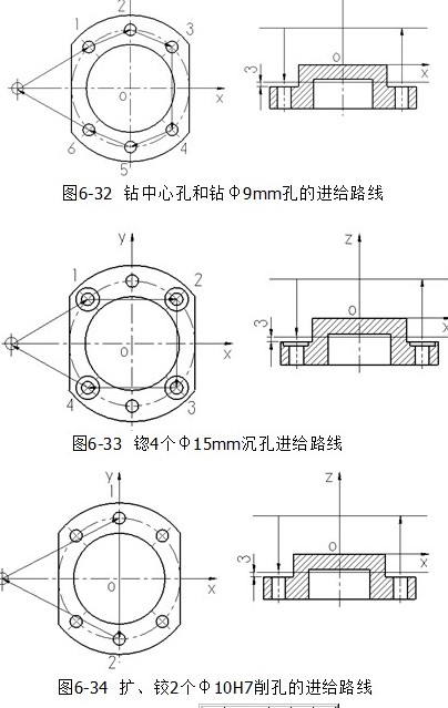
(1) Selecting the processing method The size accuracy of the two φ10H7 pin holes is IT7, and the surface roughness is Ra1.6μm. In order to prevent the drilling deviation, it is necessary to process according to the drilling center hole → drilling → reaming → reaming scheme; A φ9mm through hole is used to install the screw, so the precision requirement is low, and it can be processed according to the drilling center hole→drilling scheme; 4 φ15mm counterbore can be bored in the through hole and then back.
(2) Determining the processing sequence After selecting the processing method, the processing sequence can be determined according to the principle of tool concentration in this process. The processing sequence is the center hole of all the holes drilled → drilling → reaming → boring → reaming, specific processing The process is shown in Table 6-13.
(3) Determining the clamping scheme and the selection fixture Since the part is produced in large quantities, it can be clamped by a special fixture. Since the bottom surface, φ40H8 inner cavity and side surface have been processed in the previous process, this process can adopt φ40H8 inner cavity and bottom surface as positioning surface, and the side side plus anti-rotation pin limits six degrees of freedom, and is clamped by the pressure plate.
(4) Selecting the two φ10H7 pin holes of the tool is the drilling center hole → drilling → reaming → reaming, so φ5mm center drill, φ9mm twist drill, φ9.85mm reaming drill and φ10H7 reamer; 4 The φ15mm counterbore can be made of φ15mm boring. The selected tools are shown in Table 6-14.
(5) Determination of the feed route Since the position accuracy of each hole is not high, the feed route in the xy plane is determined by the principle of the shortest route, and the feed route in the xy plane and the z direction is as shown in Fig. 6. -32 to Figure 6-34.
Heilongjiang Junhe Building Materials Technology Co., Ltd , https://www.junhejiancai.com