
[ Huaqiang Security Network News ] 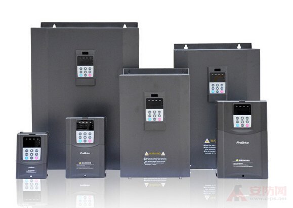
The frequency converter is a physics concept. This article introduces the definition concept and working principle of the inverter.
A frequency converter overview
Variable-frequency drive (VFD) is a power control device that controls the AC motor by changing the working frequency of the motor by applying variable frequency technology and microelectronic technology. The frequency converter is mainly composed of rectification (AC to DC), filtering, inverter (DC to AC), braking unit, drive unit, and detection unit micro processing unit. The inverter adjusts the voltage and frequency of the output power supply by the internal IGBT breaking, and supplies the required power supply voltage according to the actual needs of the motor, thereby achieving the purpose of energy saving and speed regulation. In addition, the frequency converter has many protection functions. Such as overcurrent, overvoltage, overload protection and so on. With the continuous improvement of industrial automation, inverters have also been widely used.
Two inverters work principle overview
The main circuit is a power conversion part that supplies a voltage-regulating and frequency-modulated power supply to the asynchronous motor. The main circuit of the frequency converter can be roughly divided into two types: the voltage type is a frequency converter that converts the direct current of the voltage source into an alternating current, and the filtering of the direct current circuit is a capacitor. . The current type is a frequency converter that converts the direct current of the current source into an alternating current, and the direct current loop filtering is an inductance. It consists of three parts, which converts the power frequency power supply into a "rectifier" of DC power, and absorbs the "pulse-wave loop" generated by the voltage ripple generated by the converter and the inverter.
Rectifier
A large number of diode converters are used, which convert the commercial power supply into a DC power supply. Two sets of transistor converters can also be used to form the inverter, and the regenerative operation can be performed because the power direction is reversible.
Flat wave loop
The DC voltage rectified by the rectifier contains a ripple voltage of 6 times the frequency of the power supply, and the ripple current generated by the inverter also causes the DC voltage to fluctuate. In order to suppress voltage fluctuations, the ripple voltage (current) is absorbed by the inductor and the capacitor. When the device capacity is small, if the power supply and the main circuit constitute a device with a margin, the inductor can be omitted and a simple smoothing circuit can be used.
Inverter
In contrast to the rectifier, the inverter converts the DC power to the AC power of the required frequency, and the three switching devices are turned on and off at the determined time to obtain the 3-phase AC output. The switching time and voltage waveforms are shown by taking a voltage type pwm inverter as an example.
The control circuit is a circuit that provides a control signal to the main circuit of the asynchronous motor (voltage and frequency adjustable). It has an "arithmetic circuit" of frequency and voltage, a "voltage and current detecting circuit" of the main circuit, and a "speed detecting of the motor". The circuit" is composed of a "drive circuit" that amplifies the control signal of the arithmetic circuit, and a "protection circuit" of the inverter and the motor.
(1) Operation circuit: The external speed and torque commands are compared with the current and voltage signals of the detection circuit to determine the output voltage and frequency of the inverter.
(2) Voltage and current detection circuit: It is isolated from the main circuit potential to detect voltage and current.
(3) Drive circuit: A circuit that drives the main circuit device. It is isolated from the control circuit to turn the main circuit device on and off.
(4) Speed ​​detection circuit: The signal of the speed detector (tg, plg, etc.) mounted on the asynchronous motor shaft machine is sent to the calculation circuit as a speed signal, and the motor can be operated at the command speed according to the command and calculation.
(5) Protection circuit: Detect the voltage, current, etc. of the main circuit, in order to prevent damage to the inverter and asynchronous motor when an abnormality such as overload or overvoltage occurs.
7+Person Hot Tub
7+ Person Hot Tub,large outdoor spa,outdoor living pool spa,spa with outdoor heated pool,modern outdoor hot tub
Guangzhou Aijingsi Sanitary Products Co.,Ltd , https://www.infinityedgehottub.com