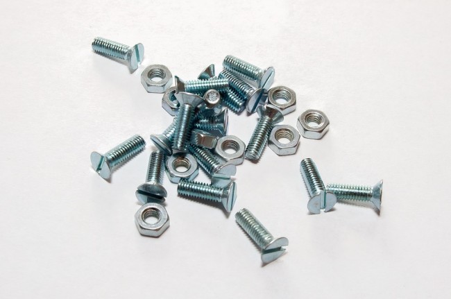
Still do not know how to calculate the bolt preload? Come check it out!

1. The bolt tensioning method generally considers the preload of KN.
The method of pulling the bolt is to directly apply an external force to the end of the bolt by using a hydraulic cylinder. Extend the bolt to the desired length and gently tighten the nut by hand to maintain the applied load. Due to the influence of bolt lubrication and the amount of thread friction, a more accurate bolt load can be obtained by the drawing method. In addition, the bolt tensioner can simultaneously stretch multiple bolts, usually using two syncs (one pump and two stretchers), four syncs (one pump and four stretchers), and eight syncs (one pump eight stretcher) ) or more, so that the entire bolt is subjected to a uniform force to obtain a balanced load. This drawing method is particularly suitable for applications requiring fastening accuracy such as key flanges. It can make the flange connection force even and prevent leakage.
The bolt tensioner consists of a cylinder, a tie rod and a support sleeve. With a 150 MPa pressure design, the disc spring is automatically repositioned and the cylinder is located on the bolt axis. It is used to axially stretch the bolts to achieve the amount of tension required for the bolts. The elongation or elongation of the bolt creates the clamping force required to tighten the bolt. When the bolt is stretched, the nut will break from the flange contact surface. There is an opening in the bottom of the support sleeve for the operator to manually turn the nut (usually the rotation of the nut is achieved by a dial provided on the outside of the nut to move the nut through the metal dial lever). After the oil pressure in the unloader is unloaded, the nut and the joint surface are rotated again, thereby locking the axial deformation of the bolt, that is, the load of the remaining bolt is locked in the bolt. The load applied to the bolt is proportional to the hydraulic pressure in the hydraulic cylinder, allowing the design to maintain the payload well. Since the load is applied directly to the bolt and all the forces are applied to the bolt extension, the space required for the load generation can be minimized.
The unique dispenser design allows multiple stretchers to be easily connected via quick couplings and tubing to balance bolt loads. The same pumping station is equal to the pressure assigned to each cylinder by the distributor, and the cylinder of the cylinder has high precision, which ensures the consistency of the bolts around the flange. The residual load/payload of the bolt is greater than the torque, so we believe that drawing is a more efficient and accurate method of fastening.
2. Bolt torque mode, the tightening torque of Nm is generally given in the design.
Bolt torque calculation methods are:
For the pre-tightening force of the general threaded connection, the torque required for the torque torque wrench is calculated as Ty=0.12δSASD(nm), where the yield limit of the δs-bolt material (MPa) is the nominal stress cross-sectional area of ​​the thread (MM2) ) d-thread NOM. Inner diameter (m).
Calculation of important thread connection torque:
For the preload of important threaded connections, the torque required for the torque torque wrench is calculated as Ty = 1.4kf0d (nm), where D - thread nominal diameter (m) F0 preload (n) is carbon steel bolt F0 = (0.6 to 0.7) δSAS(n). Tighten in alloy steel bolt F0=(0.5-0.6)δ. Torque coefficient, K value and thread geometry (diameter, lift, etc.) of surface oxidation and galvanizing, relationship between screw equivalent friction coefficient, nut and friction coefficient, K=0.1, K= 0.13-0.15, K= 0.18 -0.21, surface oxidation and galvanizing. The UK value of dry roughing table can reach K=0.3
The other can also be used to calculate the angle of the nut and adjust and adjust the torque and angle. (See the Mechanical Design Manual, Mechanical Industry Press, September 1991 for the above parameters)
The calculation of the torque is derived from the pulling force and is more convenient. However, no matter whether the bolt is old or new, there is no lubrication and other factors, the accuracy is not as accurate as the tensioner.
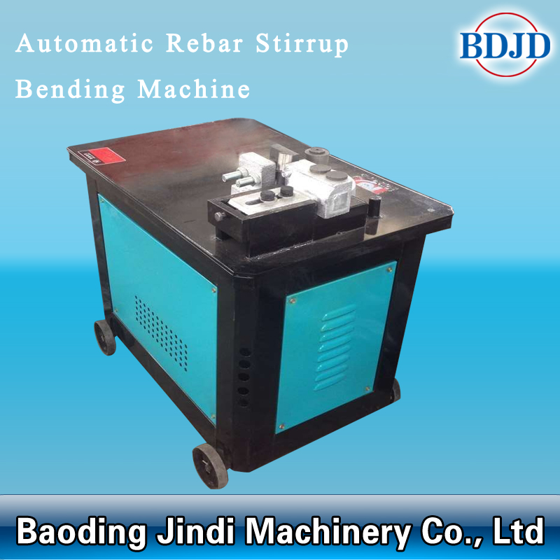
GF20/GF20CNC/GF25CNC Automatic Rebar Stirrup Bending Machine can bend round steel bar with diameter to various geometrics shape as required by construction.
Main Features Of Rebar stirrup bending machine
1. Convenient use: perfect safety performance, standard angle, fast speed, light and
handy.
2. Easy Operation: one man can operate it once switch on the power.
3. Convenient of range adjustment: for GF20 model, just need to shift induced magnet.
for GF20 CNC and GF25CNC model, just need to press the button on operation panel
4. We adopt two foot pedals: 90°and 135°, angle adjustment freely.
5. Fast Speed: rotate speed is 20-25 times/min (GF20), 25-30 times/min(GF25).

CNC Rebar Stirrup Bending Machine
Cnc Rebar Stirrup Bending Machine,Cnc Stirrup Rebar Bending Machine,Automatic Cnc Stirrup Rebar Bending Machine,New Mechanical Rebar Bending Machine
BAODING JINDI MACHINERY CO., LTD , https://www.rebarconnectors.com